

You will find various 3D Models and prints that I have made.
This Page will be updated over time as I add new ones.
Enjoy! `mike
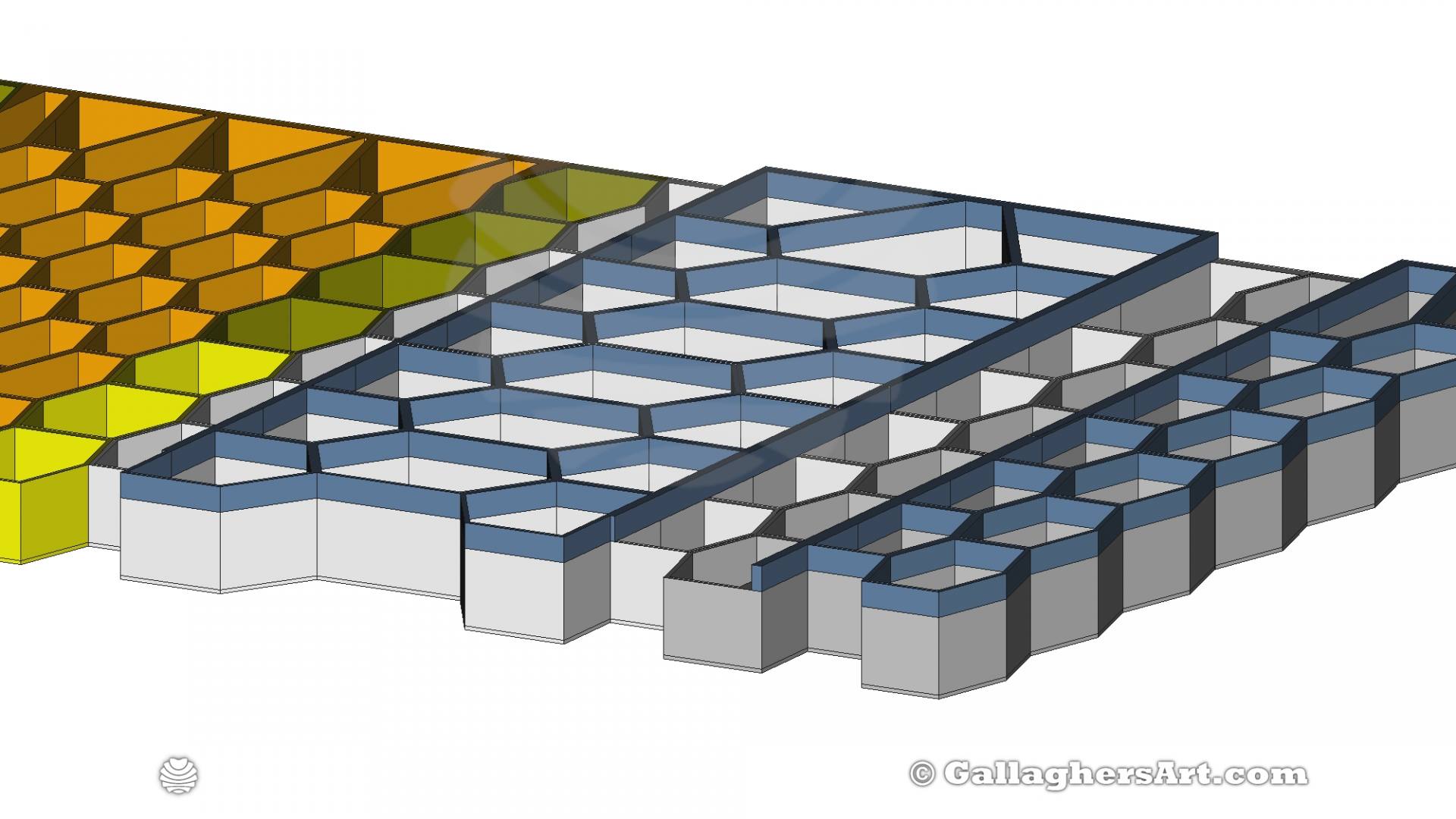
Wish I would had done it sooner, much better than in bags in a box out of site. Many others have made versions like this. Here it’s meant to be attached to a board and framed up, also using as little filament as possible. Most MINIFIGS fit in these smaller-width hexagons. Made some modules that are wider or taller.
I’m printing at
0.8mm with 0.3 thick layers. A base of 1.2mm thick is using 1.0mm lines. Box walls are 3.2mm with modules joining sides being 1.6mm (4 lines to 2 lines).
Right now wrapping in window stretch wrap, but hope glass frame.
You can add as many rows or columns. Columns come in single, triple, five, and seven boxes wide. The rows would be different styles mostly different types of 5’s and 7’s types with some fillers.
I would resize anything using FreeCAD and making changes to the Spreadsheet. Verse
resizing in slicer.
I’m sure I’ll be making other mods for this.
Raised areas for deeper boxes.
Modules that are scenes.
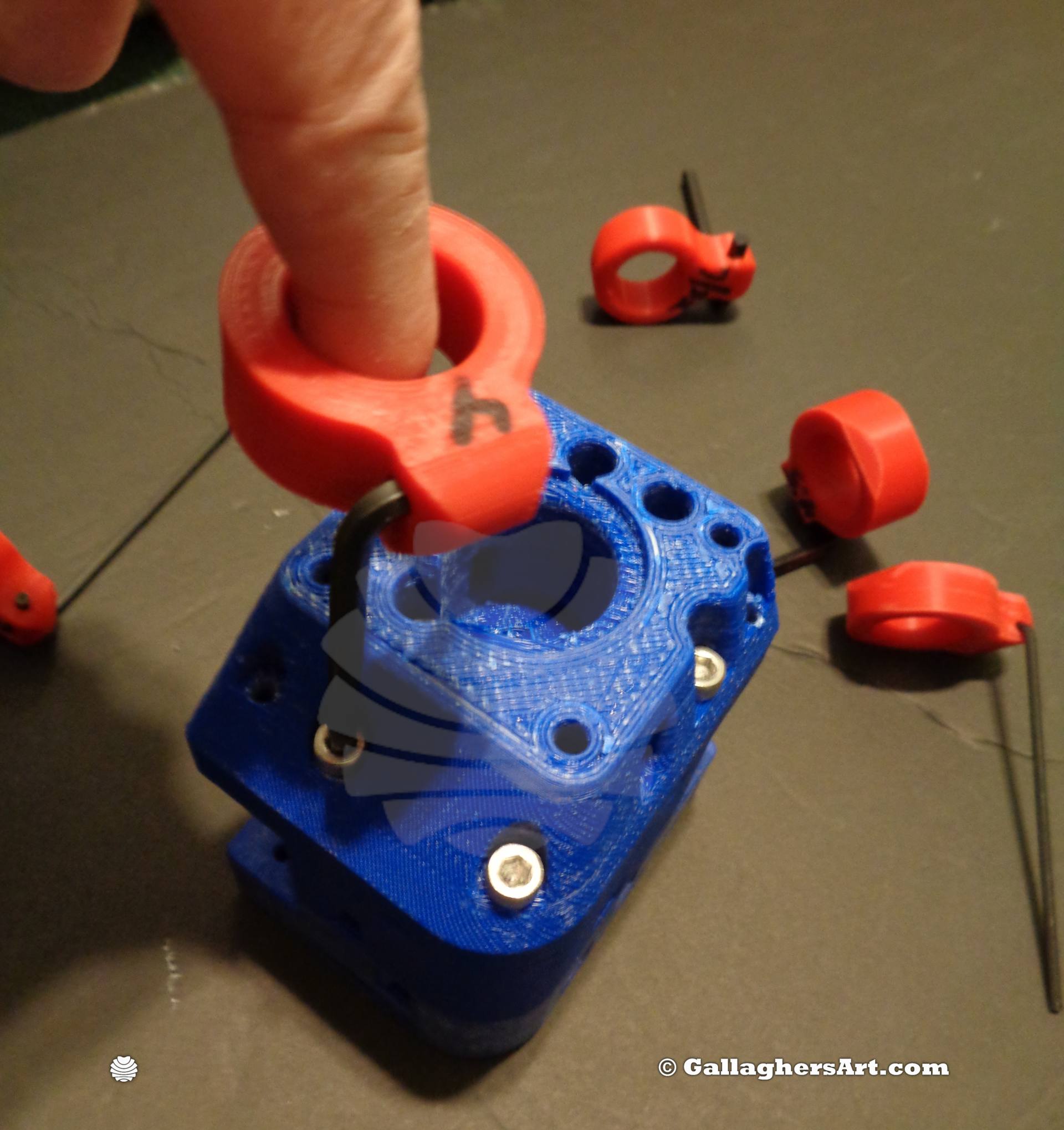
A simple add-on part to your Allen-type L wrenches allows you to use a finger to quickly insert or remove a hex bolt.
I have included several sizes. The Source Files are in FreeCAD (on my personal website) that you can modify to fit your own needs.
Each area for a finger is 23mm in diameter and is attached to an Allen key with a flat-ended 3mm grub Screw with a minimum length of 8mm.
I have added 0.4mm to each size of the Allen key for printer slop, I print using 1.0mm lines.
Sizes Included
Metric
2mm, 2.5mm, 3mm, 3.5mm, 4mm, 4.5mm, 5mm, 5.5mm, 6mm, 7mm
Inch (converted to mm)
¼” (6.35mm), 7/32” (5.55625mm), 3/16” (4.7625mm), 5/32” (3.96875mm), 9/64: (3.57187mm), 1/8” (3.175mm), 7/64” (2.77812mm), 3/32” (2.38125mm), 5/64” (1.98438mm)
Files include STL’s and STP’s. My source files (FreeCAD) are Only on my personal website
Wire management to relieve cable pressure on Ethernet Switch
Working with what I had I made an enclosure/tent for my Z9M3 CoreXY printer.
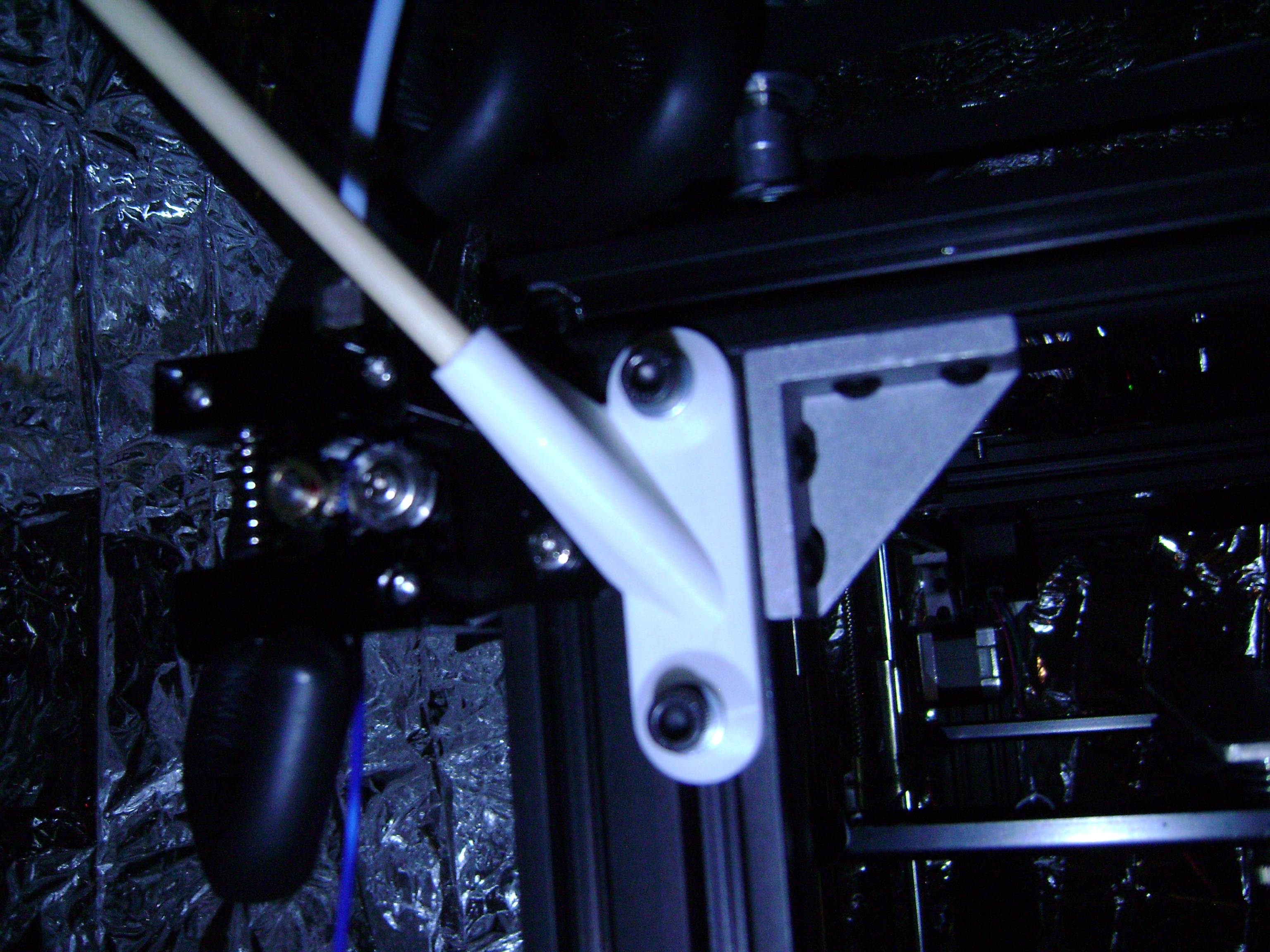
I have left and right versions of a 45degree angle for holding grill skewers that are around 6mm so some work will be needing to be done to fit. the hole is smaller than I needed, as the skewers are of varying sizes I made the hole to tightly fit the smallest I found.
Cut four skewers so they end up as tall as your filament tubes, once heated the heat will raise the roof up. I connected the side skewers with another skewer to make them sturdier.
Once the 4 parts on the unit make a tent shape out of them, some duct tape works well, just make sure no sticky tape part is left out as the emergency tent will want to stick to them.
I then added 4 magnets to each corner. The corners should be at the Hight of the filament tubes. Once closed and heated the heat will raise the roof up, so do not worry.
I used one blanket for the back and left side. (using a magnet to attach)
Then one blanket for the roof and right side.
I then place the 3rd blanker to be the front “door”.
While the room is dark and if you have lights on your bed you can see through the blankets.
No need to tape up seems and such, I may during winter, but right now in summer, the gaps allow excess heat to escape. And I can adjust these upper holes to allow heat to escape. The tents just hang, with no sealed or lower connections
With using magnets the sides can be easily removed, and if you fold from the door and right side over top, you can remove the whole unit as a single piece to place aside the unit if it is needed again.
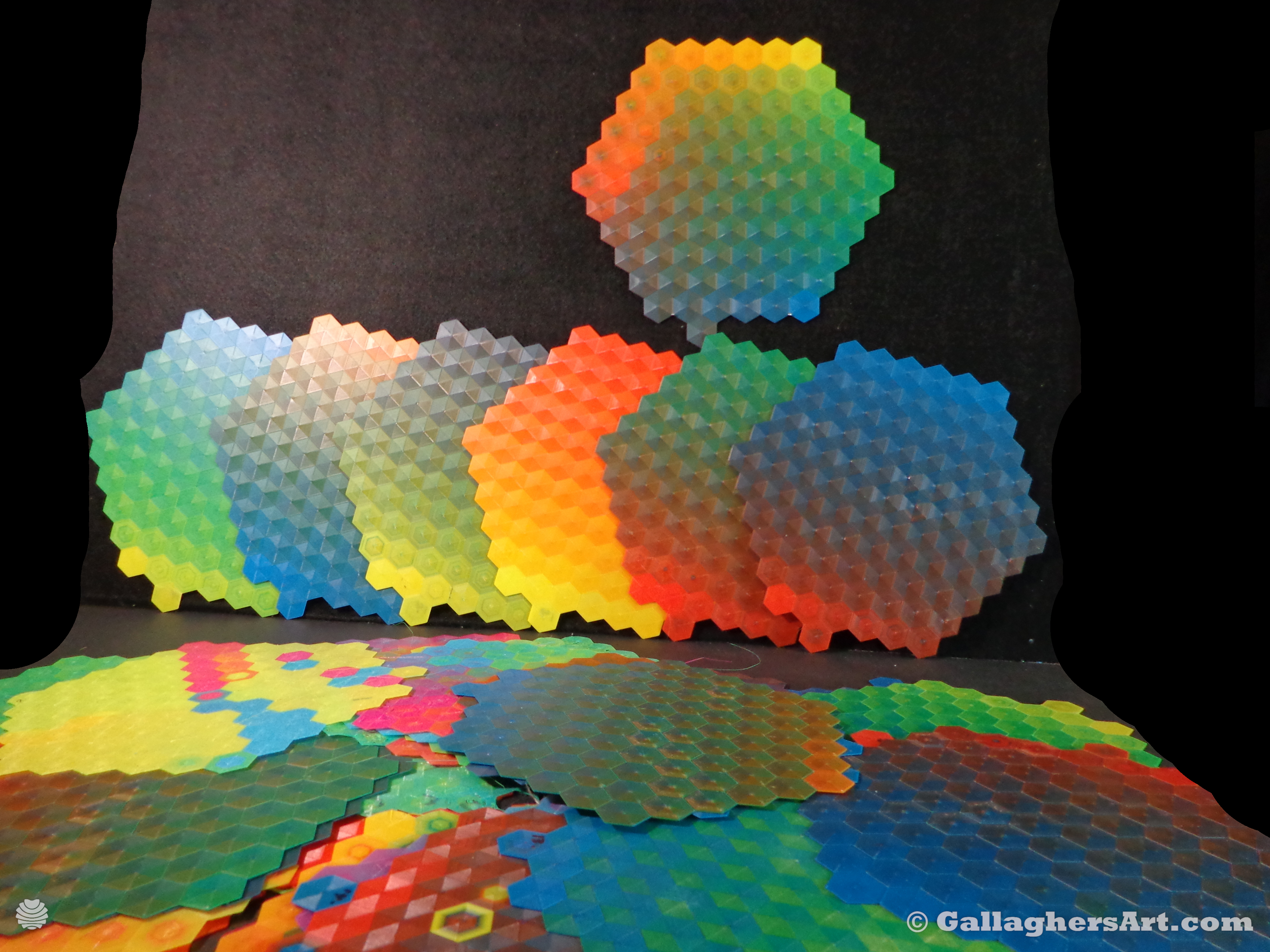
This is an updated version of my color wheel with variations.
I have a ZoneStar Z9M3 (3into1) using marlin and the source files included are just gcode I used, so you may need to adjust, need 300mmx300mm bed.
2 layers both 0.3mm. I sliced with only 1 layer, so the second is just a copy so the nozzle comes into contact with already printed 2nd layers.
1st layer is for color changing. Works good for prints going from one color to the next. But the color wheel I need to adjust a bit more, maybe 3 layers.
Images should be marked, So far I think each brand of filament will get a different color wheel.
Working on CMY, (CMYK/W, CMYKW soon) I want a red going to yellow while using CMY.
If you make or sell Filament or Mixing HotEnds I would love to test them out, send me a demo to keep and report on.
I will have more of a report with additional images and microscope images of mixed prints soon on my website, once done I will have a link here.
**Current Inland Color wheel needs adjusting on the left color changes and more yellow though out, working on that now/soon.
If you print your own, you will need to adjust the gcode manual for your unit/filaments
temps autobed level before print purge at -20y 220x
If you print your own please share, I would also love permission to share different types of prints.
Enjoy!
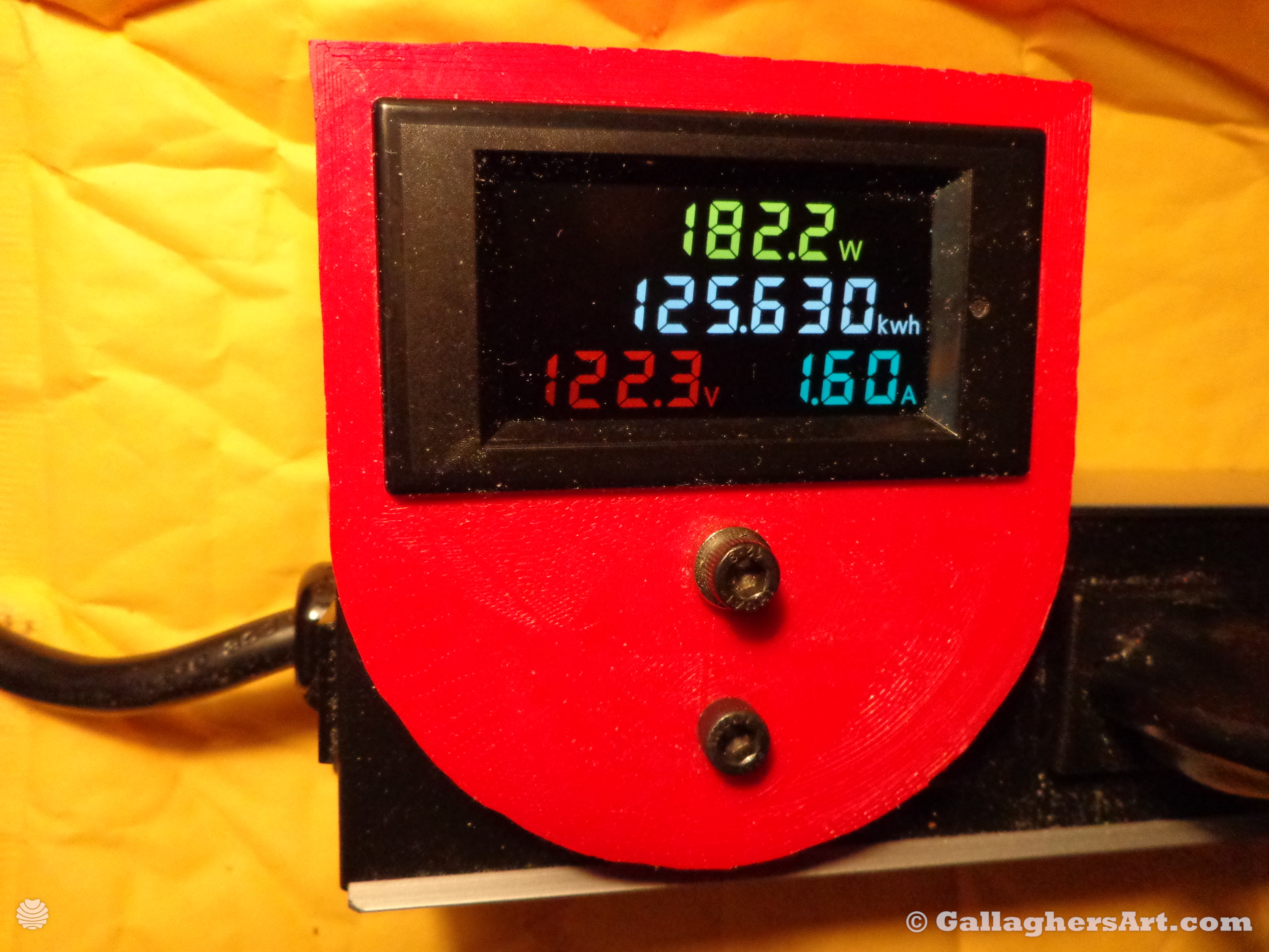
A simple Power meter was added to the side of the metal power strip.
The unit used can be found here https://www.aliexpress.com/item/LCD-Digital-Voltmeter-Ammeter-Volt-Amp-Power-Kwh-Panel-Meter-AC-80-300V-100A/32825795471.html
Need to drill 2 holes and add protection for sharp holes. One is for magnet, The other is for power.
2 M5 holes for attachment and if your power strip is metal and able to have M5 holes tapped do so or use nuts.
Once in place and secured, the printed box will cover all wires, and then attach the bottom plate to close the box.
I left the tabs of the meter to be hand filed to secure the meter in the printed unit.
Enjoy!
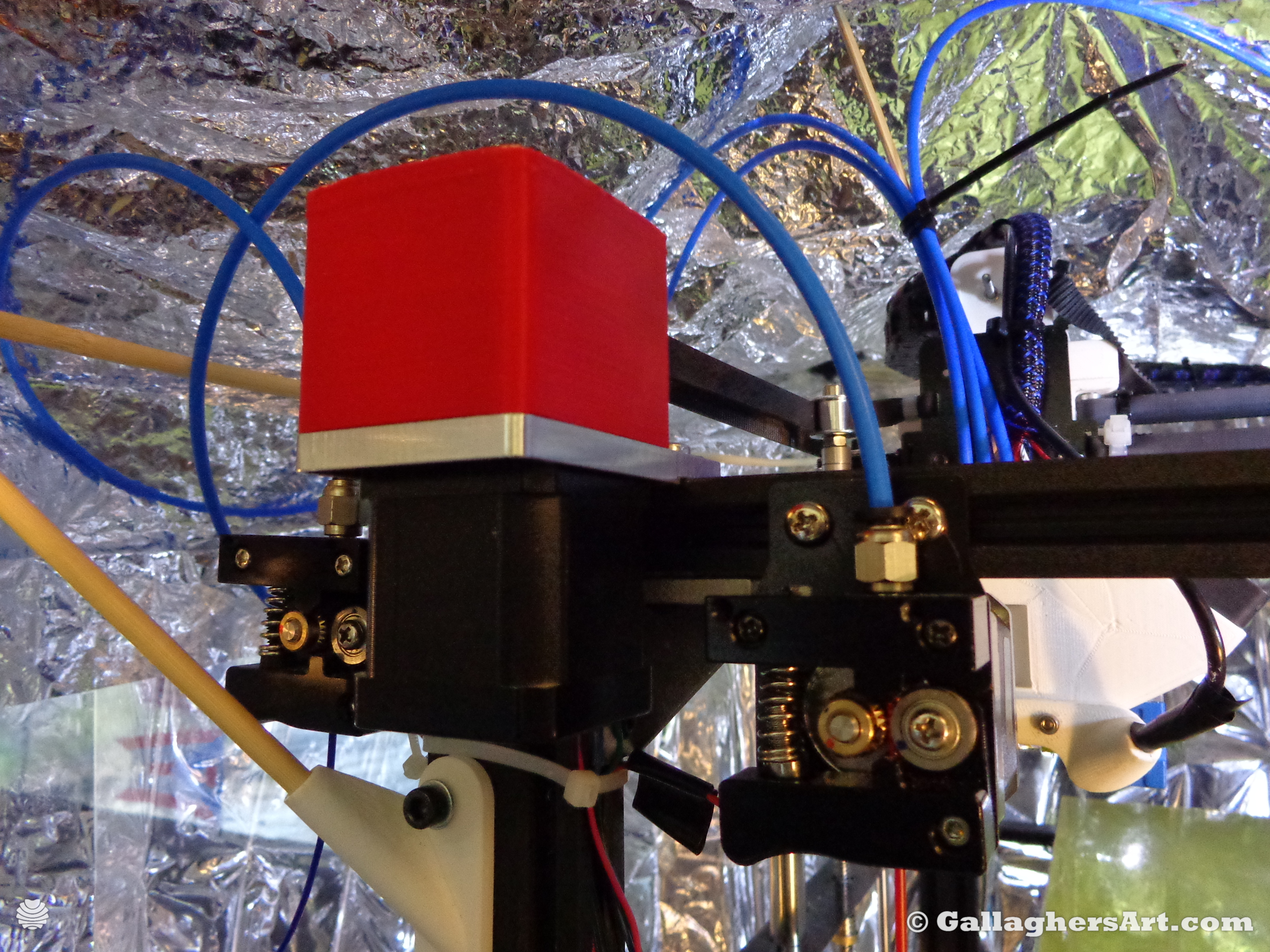
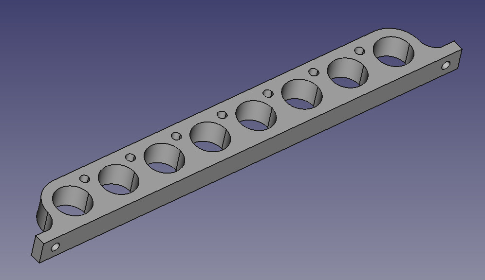
I’m using Railcores X and Y motor mounts for my CoreXY printer.
These are the lower and high belt levels X & Y motor covers.
I have my unit with the motors up front, so I have more access to the printer. The belts cross on the back.
I needed something to cover up the gears before I get my hair caught in the machine.
Also included is a drill jig template so you can correctly drill M3 hole placements. (M3 is printed)
Print also has M3 holes printed into it, which may require some pre-drilling to fit your screw size. And the printed hole depth is 10mm.
Updated and source files will be found on my website, also once I get M3 heat inserts I will update files for heat inserts. Enjoy!
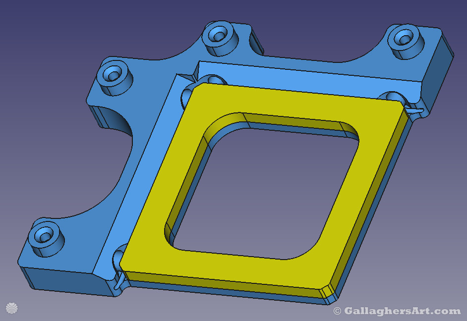
This is my take on a skew test and adjustment. 1st version works with a 152mm caliper, 2nd version will be for a larger caliper. (right now it’s just the X and Y, still need to print and test the Z options, which coming soon).
The test block is a 116mm square that prints in less than 20min. I found that the good Gates belts on my CoreXY stretch over time. So I print one of these before any prints that squareness and size matter. Down the road once I have my own 3D print farm I can have these as verification for customers to know how tight the scale and askew are.
The test rig needs to be printed on a printer all ready square. Then print test blocks on units that need adjusting. Down the road, I hope to have a metal version of the test rig milled.
How to use:
Using a large 2x4x6” machinist block zero out all 4 dial gauges. It is best to leave an mm or so of space on the side while the block is against the bottom of the test rig. This will give you some space if the text block is out of square.
Print test block.
Bulges from the base or top from the elephant effect should not matter on the test rig. (indents are made in the test rig to ignore these, so no need to sand down.) the ends are flat to measure with a caliper, with the corners rounded to give better prints. If these rounded corners still pop out you may need to carefully sand them away. You do not want to sand the areas the dial gauges meet up. If they do move the seam to another location (I use all Z seam on the left corner, as bulges on this part also have clearance from the test rig. The idea is no sanding should be done, just quick tests.
Grind down the ends of the grub screw or bolt so you do not damage your dial gauges. They should be held in place with very little force. I use M3 20mm bolts that I tighten with my fingers.
Place the test block in the test rig. Hold the block against the bottom 2 dial gauges, should be Zero. Then slide to the left until one of the 2 dial gauges reaches zero. The other dial gauge is your adjustment for X and Y.
If the top dial gauge has a positive number then enter this as a positive for (duet 3) M556 S95 X.1315 Y0 Z0 (my top gauge is reading 0.1315). IF the bottom dial gauge has a positive number then you would enter a NEGATIVE number i.e M556 S95 X-.1315 Y0 Z0.
The small test block has a distance of 95mm between dial gauges. Should be 152mm from corner to corner, 116mm sides, and 7mm thick
Z test will also be 95mm, and will post in a week or so.
Source files with FreeCAD files so you can adjust the hookup points of the dial gauges to adjust for different lengths and shaft diameters using a spreadsheet in FreeCAD.
The light Blue Cells
in the spreadsheet are to be changed to match your Dial gauges. Some changes may break the Fillet or chamfer that may need to be removed from the model tree and then added back once you get the model to your settings. If things get really weird then you may need to fix the master sketch.
The Fillet’s for the corners of the test block and also the test mount where the test block is meant to be flush to the mount are required. If not you will get minor bulges on these corners that will make measurements incorrect.
These new Cardboard rolls are good in some ways, but I can not use these on my Filament Rollers. Insert 2 of these per s
Enjoy!
`mike


sm__img_2048.png "- Org top left001 (mirror 1)sm")


